How to Read a Circuit Diagram Schematic
Learn schematic symbols, nodes, power and ground, series vs parallel, and how to trace a circuit — a clear guide for hobbyists, students, and makers.

A circuit diagram — also called a schematic — is the universal language of electronics. It is a simplified drawing that shows every component in a circuit and exactly how they connect, without worrying about where parts physically sit on a board. If you have ever opened a datasheet, a repair manual, or a DIY electronics tutorial and felt lost in a maze of lines, zig-zags, and cryptic labels, this guide is for you.
Learning how to read a circuit diagram schematic unlocks the ability to build projects, troubleshoot faults, and understand how real devices actually work. By the end of this guide you will recognize the most common schematic symbols, follow a signal from power to ground, tell series from parallel, and trace a complete circuit from start to finish. No prior electronics background is required.
What is a circuit diagram schematic?
A schematic is a symbolic representation of an electrical circuit. Instead of drawing a photograph of each part, engineers use standardized symbols connected by lines that represent wires. The goal is clarity: a schematic shows the logical relationships between components — what connects to what — rather than their real-world size, shape, or position.
It helps to know how a schematic differs from three other drawings you will encounter:
- Pictorial diagram: Uses realistic pictures of components. Friendly for absolute beginners, but impractical for anything complex.
- Wiring diagram: Shows the physical routing of wires and terminals, common in automotive and appliance repair.
- PCB layout: Shows where components physically sit on a printed circuit board and how copper traces run between them.
The schematic is the master blueprint. The PCB layout and wiring diagram are derived from it. Because schematics use the same internationally recognized symbols, a schematic drawn in Tokyo can be read by an engineer in Toronto without translation.
Why learning to read schematics matters
Reading schematics is the single most transferable skill in electronics. Whether you want to assemble a kit, repair a guitar pedal, follow an Arduino tutorial, or design your own product, everything starts with the schematic. It lets you predict how a circuit behaves before you touch a soldering iron, identify which component to check when something fails, and communicate your ideas precisely with other people.
Think of it as sheet music for electronics: once you can read it, an entire library of designs opens up to you.
The building blocks: schematic symbols you need to know
Every schematic is built from a small vocabulary of symbols. Master a dozen of them and you can read the vast majority of hobby and consumer circuits.
Figure 1: Common schematic symbols. Note the two resistor styles — the zig-zag (ANSI/US) and the rectangle (IEC/Europe) mean the same thing.
A few symbols cause the most confusion at first:
- The resistor appears either as a zig-zag line (American ANSI) or as a plain rectangle (international IEC) — both mean exactly the same thing.
- A capacitor is two parallel lines; if one line is curved or marked with a "+", it is a polarized capacitor that must be installed the right way round.
- A diode is a triangle pointing at a line, and current can only flow in the direction the triangle points.
- The LED adds two little arrows to show it emits light.
Reference designators: the letters next to each symbol
Every component carries a label made of a letter and a number, such as R1, C4, or Q2. The letter is a reference designator that tells you the type of part, and the number simply distinguishes multiple parts of the same type. Alongside the designator you will usually see a value, like "10 kΩ" for a resistor or "100 μF" for a capacitor.
| Designator | Component | Unit | What it does |
|---|---|---|---|
| R | Resistor | Ohms (Ω) | Limits current flow |
| C | Capacitor | Farads (F) | Stores charge, blocks DC, passes AC |
| L | Inductor | Henries (H) | Stores energy in a magnetic field |
| D | Diode / LED | — | Lets current flow one direction only |
| Q | Transistor | — | Switches or amplifies signals |
| U / IC | Integrated circuit | — | A chip containing many components |
| SW | Switch | — | Opens or closes a connection |
| J / P | Connector | — | Interface to other boards or wires |
| BT | Battery | Volts (V) | Supplies DC power |
| F | Fuse | Amps (A) | Breaks the circuit on overcurrent |
Reading component values and notation
A symbol tells you what a part is; the value tells you how it behaves. Values appear next to the reference designator and follow a few conventions worth knowing.
Resistors use ohms with the multipliers k (kilo, ×1,000) and M (mega, ×1,000,000), so "4k7" or "4.7k" both mean 4,700 ohms — notice how the letter can replace the decimal point. Capacitors use farads, almost always with μ (micro), n (nano), or p (pico) prefixes because a full farad is enormous; "100n" is 100 nanofarads. Inductors use henries with the same style of prefixes.
On real resistors the value is often printed as colored bands rather than numbers, and the schematic will still show the plain value. When a schematic lists a part only by a designator like "U3" with no value, that means it is a specific chip and you should look up its part number in the bill of materials or the accompanying datasheet.
Wires, nodes, and the most important rule of all
Lines on a schematic represent wires — ideal, zero-resistance connections between components. Here is the rule that trips up almost every beginner: two crossing lines are only connected if there is a solid dot at the intersection. That dot is called a junction or node. If two lines cross with no dot (or with a small "hop" over one another), they are simply passing by and are not electrically connected.
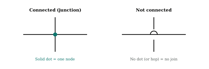
Figure 2: A solid dot means the wires are joined into one node. No dot means the wires cross without touching.
Any set of wires joined together forms a single node, and every point on that node is at the same voltage. Recognizing nodes is the key to tracing a circuit, because current flows from node to node through components. When you get comfortable, you will stop seeing individual wires and start seeing nodes.
Power and ground: where everything begins and ends
Almost every circuit has a power source and a ground reference. Power is often labeled VCC, VDD, V+, or with a voltage such as "+5V". Ground — the common return path and 0 V reference — is marked GND or drawn as a downward stack of shrinking horizontal lines.
To save clutter, designers rarely draw a wire all the way back to the battery; instead they place a ground symbol wherever the connection is needed. Every ground symbol on the sheet is electrically the same node. Reading a schematic becomes much easier once you accept that current leaves the positive supply, travels through the components doing useful work, and returns to ground.
Series vs. parallel connections
Two components are in series when they sit one after another on the same path, so the same current flows through both. They are in parallel when they share the same two nodes, giving current more than one path to travel and placing the same voltage across each component. Spotting these arrangements at a glance helps you understand how voltage and current divide across a circuit.
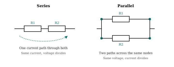
Figure 3: In series (left) one current path runs through R1 and R2. In parallel (right) R1 and R2 each get their own path across the same two nodes.
Step by step: reading a simple circuit
Let us put it all together with a classic first circuit — a battery lighting an LED through a current-limiting resistor.

Figure 4: A 9 V battery drives an LED through a 470 Ω current-limiting resistor.
- Find the power source. The battery (BT1) on the left supplies 9 V. The longer line of the symbol is the positive terminal.
- Follow the current from positive. Trace the wire out of the positive terminal. It leads to R1, the 470 Ω resistor.
- Identify each component in the path. After the resistor the wire reaches the LED. The resistor limits the current so the LED is not destroyed.
- Check component orientation. The LED’s triangle points in the direction of current flow (from + toward ground). If it were reversed, no current would flow and the LED would stay dark.
- Return to the source. From the LED the wire continues back to the negative terminal of the battery, completing the loop. A circuit only works when it forms a complete, unbroken loop.
That five-step method — find power, follow the current, identify each part, check orientation, return to the source — scales up to circuits with hundreds of components. Complex designs are just many small loops sharing common power and ground nodes.
Tips for reading complex schematics
- Work in functional blocks. Large schematics are grouped into stages — power supply, input, processing, output. Identify the blocks first, then read each one.
- Follow the signal, not the layout. Read left to right, input to output, the way the designer intended, rather than jumping around the page.
- Use the net labels. Named wires like "SDA", "RESET", or "MOSI" connect to every other wire with the same name, even across pages. This keeps big drawings readable.
- Keep the datasheet open. For any IC (a "U" designator), the datasheet explains what each pin does — essential for making sense of the chip.
- Trust the dots. When in doubt about a connection, look for the junction dot. No dot, no connection.
Common mistakes beginners make
Three errors account for most confusion:
- Assuming crossing wires are connected — always look for the dot.
- Ignoring polarity on diodes, LEDs, electrolytic capacitors, and ICs; these parts only work when oriented correctly, and the schematic always tells you which way.
- Forgetting that the circuit must form a complete loop back to the source.
If you can keep those three ideas straight, you have avoided the pitfalls that frustrate most newcomers.
Frequently asked questions
Is a circuit diagram the same as a schematic?
Yes. "Circuit diagram," "schematic diagram," and "schematic" all refer to the same thing: a symbolic drawing of how a circuit’s components connect. A wiring diagram or PCB layout is different — those show physical placement rather than logical connections.
How long does it take to learn to read schematics?
You can read simple circuits after an afternoon of study. Recognizing the dozen most common symbols and understanding nodes, power, and ground gets you most of the way. Fluency with complex, multi-page industrial or IC-heavy schematics comes with months of practice.
What do the numbers and letters like R1 or 10k mean?
The letter-and-number label (R1, C2, Q3) is a reference designator identifying the part type and giving it a unique ID. A separate value such as "10k" (10 kilohms) or "100μF" tells you the component’s electrical rating.
Why do some resistors look like rectangles and others like zig-zags?
They are two drawing standards for the same component. The zig-zag is the American ANSI symbol; the rectangle is the international IEC symbol common in Europe and Asia. Both mean "resistor."
Do I need to know math to read a schematic?
No math is required just to read and trace a circuit. Basic Ohm’s law (V = I × R) helps you understand why components have the values they do, but you can follow the logic of a schematic without any calculation.
How to practice and get faster
Reading schematics is a skill built through repetition. Start with the simplest circuits you can find — a flashlight, a single-transistor amplifier, a 555 timer blinker — and trace every loop by hand before moving on.
Free simulators such as Falstad’s circuit simulator, Tinkercad Circuits, and CircuitLab let you draw a schematic and immediately watch current flow, which builds intuition far faster than reading alone. Design tools like KiCad and EasyEDA are free and let you open real project schematics to study how professionals organize a page into functional blocks.
A powerful exercise is to take a schematic and build it on a solderless breadboard. Translating the abstract drawing into physical components forces you to understand every connection, and seeing the circuit actually work cements the knowledge.
If you want to generate practice schematics from a plain-English prompt — for example "555 timer LED blinker on a 9V battery" — try Circuit Diagram Generator. You can also start a free trial and turn ideas or sketch photos into editable, simulation-ready diagrams.
Conclusion: start reading, start building
Reading a circuit diagram schematic comes down to a handful of habits: recognize the standard symbols, treat joined wires as single nodes, find power and ground, tell series from parallel, and trace each loop from source back to source. None of it requires special talent — only a little practice.
Print out a few simple schematics, trace the current with your finger or a highlighter, and build one of them on a breadboard to see the drawing come to life. Once the symbols become second nature, you will read electronics the way you read text: fluently, and without thinking about the alphabet at all.
Try it on your next circuit
Describe a circuit or upload a sketch — get an editable schematic in minutes.