Choosing a Current-Limiting Resistor for an LED
A practical, math-first guide to sizing the resistor that keeps an LED from burning out — with worked examples for a 9V battery and a 5V USB supply, a forward-voltage reference table, and the power-rating check most people skip.
Why every LED needs a series resistor
An LED is a diode, not a simple resistive load. Once the voltage across it reaches the forward voltage (Vf), current rises extremely steeply for tiny further increases in voltage — the I-V curve is nearly vertical there. Wire an LED straight across a battery with nothing else in the circuit and there is nothing capping that current: it climbs until the die overheats and the LED fails, often within seconds. A resistor in series gives the circuit a defined, safe current regardless of small manufacturing variation in Vf between individual LEDs.
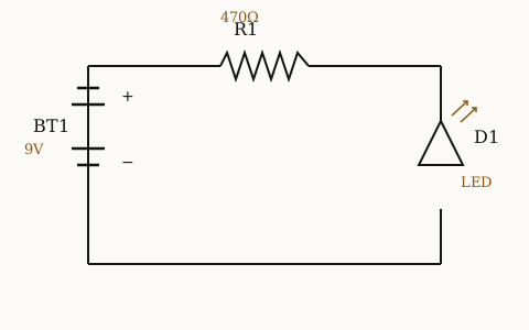
Here's the basic topology — battery, resistor, LED, all in one loop:
The formula
R = (Vs − Vf) / If
Vs is your supply voltage, Vf is the LED's forward voltage at your target current, and If is the current you want flowing through the LED. This is just Ohm's law applied to the resistor's share of the voltage.
Step 1: find your LED's forward voltage
Vf depends on the semiconductor material, which varies by colour. If you have a datasheet, use its value at your intended current. If not, these typical ranges for 5mm through-hole LEDs work as a starting point:
Red: 1.8–2.2 V Orange: 2.0–2.2 V Yellow: 2.0–2.2 V Green (standard): 2.0–3.2 V Blue: 2.8–3.4 V White: 2.8–3.6 V UV: 3.0–3.4 V
Blue and white LEDs use an InGaN junction with a noticeably higher Vf than the GaAsP junction in red/yellow/orange LEDs — that's why you can't just reuse a resistor value across colours.
Step 2: know your supply voltage
Common cases: a single AA/AAA cell is 1.5V, a coin cell is 3V, a 9V battery is 9V, USB and most Arduino boards supply 5V (3.3V on some logic pins). Check that Vs is comfortably above Vf — a single 1.5V cell can't drive a white LED (Vf ~3.2V) at all without a boost converter, no matter what resistor you pick.
Step 3: pick your target current
Standard 5mm indicator LEDs are usually rated for a 20mA absolute maximum continuous current. Most look plenty bright at 10–15mA, which also extends lifespan and reduces heat. High-brightness LEDs may tolerate up to 30mA — check the datasheet's absolute maximum and design to roughly 70–80% of it, not right at the edge.
Worked example 1: red LED on a 9V battery
Vs = 9V, Vf = 2.0V, target If = 15mA (0.015A).
R = (9 − 2.0) / 0.015 = 466.7Ω
The nearest standard E12 resistor value is 470Ω. Rounding up (rather than down to, say, 390Ω) slightly reduces current instead of increasing it — safer by default. Actual current at 470Ω: (9 − 2.0) / 470 = 14.9mA, effectively on target.
Worked example 2: white LED on 5V USB
Vs = 5V, Vf = 3.2V, target If = 20mA (0.02A).
R = (5 − 3.2) / 0.02 = 90Ω
The nearest E12 values are 82Ω and 100Ω. Pick 100Ω, rounding up: actual current becomes (5 − 3.2) / 100 = 18mA. Rounding down to 82Ω would instead push current to 22mA, over your target and closer to the rated max.
Rounding to a standard value
Off-the-shelf resistors come in preferred series (E12: 10, 12, 15, 18, 22, 27, 33, 39, 47, 56, 68, 82, 100…; E24 has twice as many steps). You will essentially never land on your exact calculated value. The rule: when the calculated value falls between two standard ones, round up in resistance. That lowers current slightly rather than raising it — the safe direction for LED longevity.
Checking the power rating
Don't skip this. P = I² × R.
Example 1: 0.015² × 470 = 0.106W. A standard quarter-watt (0.25W) resistor has better than 2x headroom — comfortable. Example 2: 0.018² × 100 = 0.032W. Trivial for a quarter-watt resistor; even an eighth-watt part would cope, though quarter-watt is more commonly stocked.
As a rule of thumb, choose a resistor rated at least double your calculated dissipation, so it runs cool and its value doesn't drift with heat over time.
Series vs parallel: never share one resistor across LEDs
Wiring several LEDs in parallel behind a single shared resistor is a common mistake. Even LEDs from the same reel have slightly different Vf; whichever one has the lowest Vf draws more current, heats up, drops its Vf further, and draws even more — it can fail while its neighbours stay dim. Give each parallel branch its own resistor.
For LEDs in series, sum the Vf values instead: three red LEDs (2.0V each) in series is 6.0V total. On a 9V supply at 15mA: R = (9 − 6.0) / 0.015 = 200Ω, rounded to the standard value 220Ω.
Common mistakes
- Running an LED directly off a coin cell with no resistor "because it worked" — the cell's own internal resistance was accidentally limiting current; it will not protect the LED from a lower-impedance source like a bench supply or USB.
- Reusing a resistor value calculated for one colour LED on a different colour without recalculating Vf.
- Rounding down to chase maximum brightness, pushing current past the datasheet's rated maximum.
- Skipping the power-rating check on low-voltage, higher-current strings, and using an undersized resistor that runs hot and drifts.
Do the calculation, round up, check the wattage, and give every parallel branch its own resistor — that covers the vast majority of LED-burnout cases.